

after almost an year of collecting parts and knowledge I finally completed the steering wheel paddles mod on MY11 V60.
There are multiple ways to achieve the goal and I will try to share as much of the info I have so far.
Be prepared for BIG pictures! ")
:Prerequisites:
1. Steering wheel with pads.
I decide to completely change my steering wheel, instead of just getting the paddles, so I purchased a steering wheel from a crashed 2017 RDesign car.
It came with the paddles and the cable inside of it. Here how it looked like. It had only ~ 14k KM on it and is like new. If you decide to get only the pads and install them on your existing steering wheel, you will have to change the cable inside of it.

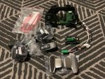
2. Gear Shift Assembly from 2014+ car. 31367921
It is required to change your existing Gear Shift Assembly as the early models don’t have the pads functionality preloaded in them. If you have a 2013 P3 car from the NA market, you will have a nice illuminated Gear Shift Assembly. Unfortunately that model will not work with the pads. If you would like to keep the nice illuminated knob, you can try to replace only its circuit board. From what I hear from some Volvo sources, it is possible to replace the old circuit board with a new one and keep your old knob.

3. Volvo repair wires with number 30656698.
You need 2 of those.

The SOLDER way of connecting the pads.
First we have to remove the steering wheel airbag. Turn the wheel 90 degrees to one side and you will be able to see a small hole on the back of it.


Insert a flat head screwdriver in and moving it downwards pry the metal pin that holds the airbag from one side. It is difficult initially to get this movement of the screwdriver right. Don’t force it too much, the pin needs very little force. If nothing is happening and you are pushing like crazy – stop and re position the screwdriver. Play with it until you get it. That was the most difficult part for me.
Once you have it popped out from one side, move the steering wheel to the other side and repeat. When you are done on that side too, turn the steering wheel to its normal position, with out pushing the airbag back in its place and go disconnect your battery. This is what VIDA says to do before you remove the airbag cables.
Once the battery has been disconnected, you can remove the airbag by disconnecting the 2 cables attached to it. Remove the top and bottom plastic cover around the steering wheel column. Top part is just clipped on, while the bottom part has 3 torx 25 screws holding it.
Once you have removed the airbag, unscrew the bolt marked on the next picture. You will need it, to secure the steering wheel angle sensor after you remove the steering wheel.

Disconnect the green connector from the steering wheel angle sensor.

Undo the big bolt holding the steering wheel and remove it.
Now use the small bolt you removed from the steering wheel plastic to secure the steering wheel angle sensor.

Remove the Steering Wheel Angle Sensor by removing the 4 screws holding it.

Now you have to remove the wipers and turn signal levers. Each one has two screws on its side holding it. Also you have to disconnect their connectors from the back of the SWM. Then they just slide off.

This is how the SWM module looks secured on the Steering wheel column. You have to remove the two screws holding it, to remove it. Also disconnect the green and yellow connector on the left side of the Steering wheel column.


Here are the PINS that have to be worked on.

Take the SWM to your bench and lets prepare the wires for it.
You have to connect the 30656698 cables to some extension wires. Use similar gauge wires and the Volvo cables.
Here is the technique I used. Splice them, Solder them, Cover them.


I used more wire then it was needed. Around 20 to 30 cm of wire should be enough.
Now solder the wires to the SWM.
Here is the tricky part. PIN number 7 on the SWM has to be completely disconnected from the rest of the board. This means you have to remove the top green layer of epoxy and the next copper layer that surrounds the pin. I used a Dremel 3000 tool to remove the layers. You have to be extremely careful not to damage any other component on the board with the Dremel. Then solder the two wires on the SWM. The new wires have to be clear of any exposed copper around PIN 7. Use a Digital Multimeter to check that PIN 7 is completely disconnected from the rest of the board.
Here how it looks like:


Now go back to the car and install the SWM back in.
You can route the new wires on the top right corner of the plastic that holds the SWM.

Then route the wires to the GSM module of the Gear Shift Assembly


Plug the two wires in the GSM green connector. You can access it just by pulling the lowest plastic cover on the left side of the Gear Shift Assembly.
Pins 1, 2, 3 and 6 will be taken on the GSM connector. You have to connect the wire from SWM 5 to GSM 4 and SWM 7 to GSM 5.
Press them in so they are inside of the connector and connect it back to the GSM.
Put everything back together.

And here is the pads working
The NO SOLDER way of connecting the pads.
You will have to buy a new SWM with both levers from a 2014+ car.
I hope this will help some of you to get the pads working on your cars.
If you have questions let me know.